TR EN
Industrial
Hygienic

Instrumentation
Hygienic / Alfa Laval  / Sanitary Valves and Automation Items / Regulated Valves / Unique RV-ST Regulating Valve
/ Sanitary Valves and Automation Items / Regulated Valves / Unique RV-ST Regulating Valve
UNIQUE RV-ST REGULATING VALVE
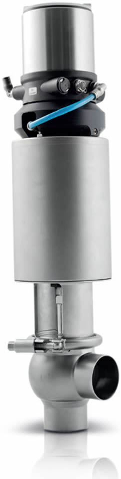 | IMPLEMENTATION Unique RV-ST is a 2nd generation product of Alfa Laval single seat regulation valves. It has been designed to address the highest needs of hygienic and safe processes. It is founded on a body that has achieved more than a million sales, and is ideal for use in high-flow hygienic liquid processes that require precise low rate control or pressure. OPERATION PRINCIPLE The valve is controlled by an electric, digital, pneumatic process control unit. It is a reliable valve with few parts that are easy to remove. STANDARD DESIGN It has been designed to reflect the reliable performance of years, and offers highly precise product control at standards with its special actuators and cone-shaped valve body that extensively uses stainless steel. It robust and long-lasting plastic body parts eliminate the breaking of metal. Valve body has been connected to the actuator shaft with a union fitting to prevent use of additional fittings, which has allowed complete integration. Product contact gaskets are standard gaskets that are used in the whole Unique series. Fittings at the end of the actuator or cylinder ensures perfect compatibility. Max. Product Pressure ............................... 10 bar (1000 kPa) Min. Product Pressure ................................ Full Vacuum Temperature Range .................................... 10°C to +140°C (EPDM) Air Pressure ................................................ 5 - 7 bar (500 to 700 kPa) PHYSICAL DATA Parts that come into contact with the product .............................. 1.4404 (316L) External Coating ......................................... Semi-lustrous Internal Coating .......................................... Lustrous, Internal part Ra < 0.8 μm Other Steel Parts ........................................ 1.4301 (304) Gaskets ....................................................... EPDM Other Gaskets ............................................. NBR |
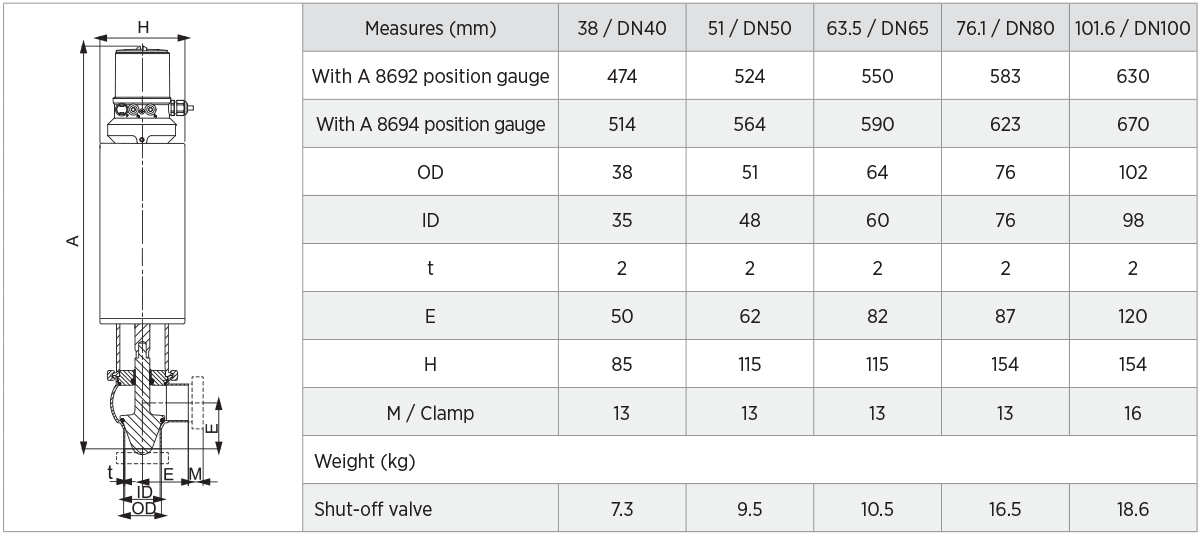
| 8692 POSITION GAUGE VISUAL TOP-LEVEL CONTROL Signal Setting ............................. 0/4 20 mA and 0 to 5 5/10 V Input Resistance ........................ 0/4 to 20 mA: 180 Ω 0 to 5/10 V: 19 Ω Power Consumption ................... < 5 W Cable Length ............................. 2 x M16 x 1,5 (cable-ø10mm) Max. Cable Diameter ................ 1.5 mm2 | POSITION GAUGE Material ....................................................... PPS, stainless steel Coating......................................................... PC Gaskets ....................................................... EPDM Power voltage.............................................. 24 VDC +/- 10% Operating Temperature ............................... 0 to 55 °C Fitting Parts ................................................. ø6 mm or 1/4” Protection Class ......................................... IP65 and IP67 Pos. Monitoring Module .............................. Contactless, Non-corrosive Communication ........................................... Analogue |
| 8694 POSITION GAUGE NON-VISUAL BASIC CONTROL Signal Setting ............................. 0/4 to 20 mA Input Resistance ......................... 180 Ω Power Consumption ................... < 3,5W Cable Length .............................. 2 x M16 x 1,5 (cable-ø10mm) Max. Cable Diameter .................. 1.5 mm2 | Valve Body Combinations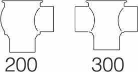 |
| OTHER VALVES WITH THE SAME BASIC DESIGN - Hygienic Unique Single Seat Valves - Standard Valves - Reverse Moving Valves - Long Stroke Valve - Manual Valves - Aseptic Valves | OPTIONS a. Male or clamp liner at standard dimensions b. HNBR or FPM for gaskets coming into contact with the product c. Sustainable Actuator d. Polished external surface coating e. Optional gaskets HNBR or FPM |
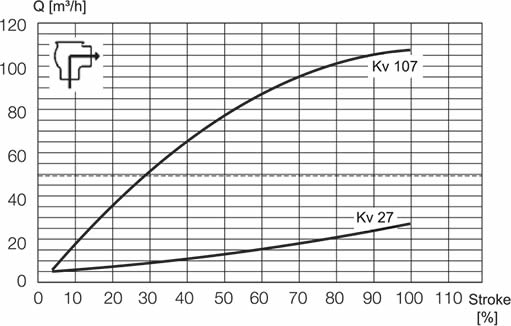
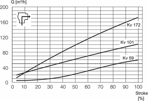
PRESSURE DECREASE/CAPACITY DIAGRAMS | |
Valve Size 1.5” | Valve Size 2” |
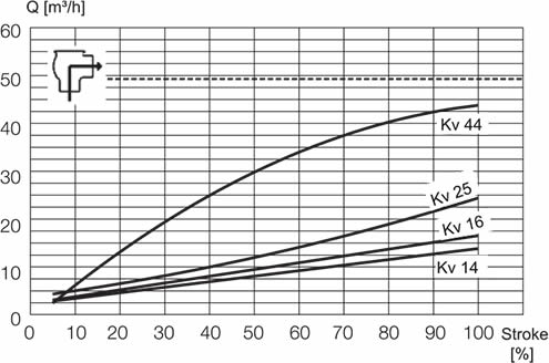 |  |
Valve Size 2.5” | Valve Size 3” |
 |  |
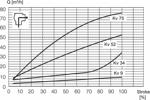
Valve Size 4” | |
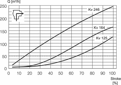 | Not: Applicable rules for these diagrams: Average: Water (20° C/68° F) Sizing: Compliant with VDI 2173 Alfa Laval recommends a maximum flow rate of 5 m/s in tubes and valves. |
| PRESSURE DATA Table 1 - Shut-off Valves Max. Pressure Without Leaking in Valve Seat in Bars |
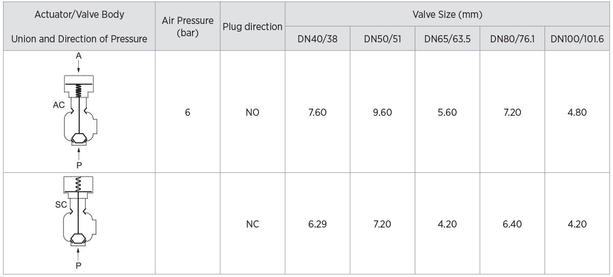 |
| A: Air, P: Product Pressure, AC: Air Closed, SC: Spring Closed |
| Use of Data to Determine Valve Size After identifying the Kv factor for a specific application, find this factor on the previous page. Choose the curve that is the nearest to 50% impact. If we use the example above, you can see the (49) Kv factor in the table on the previous page. You can see that a 2” valve intersects with 1 Kv curve. 2½” 1 curve, 3” 3 curve and 4” 3 curve is intersecting. In this example a 2” valve is the accurate choice because 49 Kv intersects nearest to 50% which is the ideal operating point. As an alternative, a 4” valve also appears near 50%.Vana Boyutlandırma Akış Katsayısı (Kv) Alttaki formül ve akış katsayısı değerleri uygulamalarınız için en doğru regülasyon vanasını seçmenize yardımcı olacaktır. Su ve özgül ağırlığı 1.0 olan diğer ürünler için formül: Kv = Q √Δ P Özgül ağırlığı 1.0 dan farklı olan ürünler i.in formül: Kv = Q √Δ P/SG | Example of Kv Calculation: Find the valve size required for 60 m3/h water. Internal pressure 3 bars External pressure 1,5 bar Solution: Internal Pressure (A) minus external pressure (B): ∆ P = 3 bar - 1,5 bar = 1,5 bar 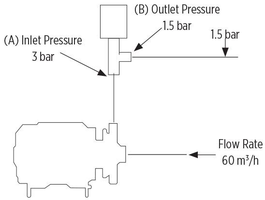 Q = Flow rate of product per hour (m3 ) SG = Specific Weight of Product ∆ P = Pressure loss inside the valve (bar) (Internal Pressure – External Pressure) |
 |
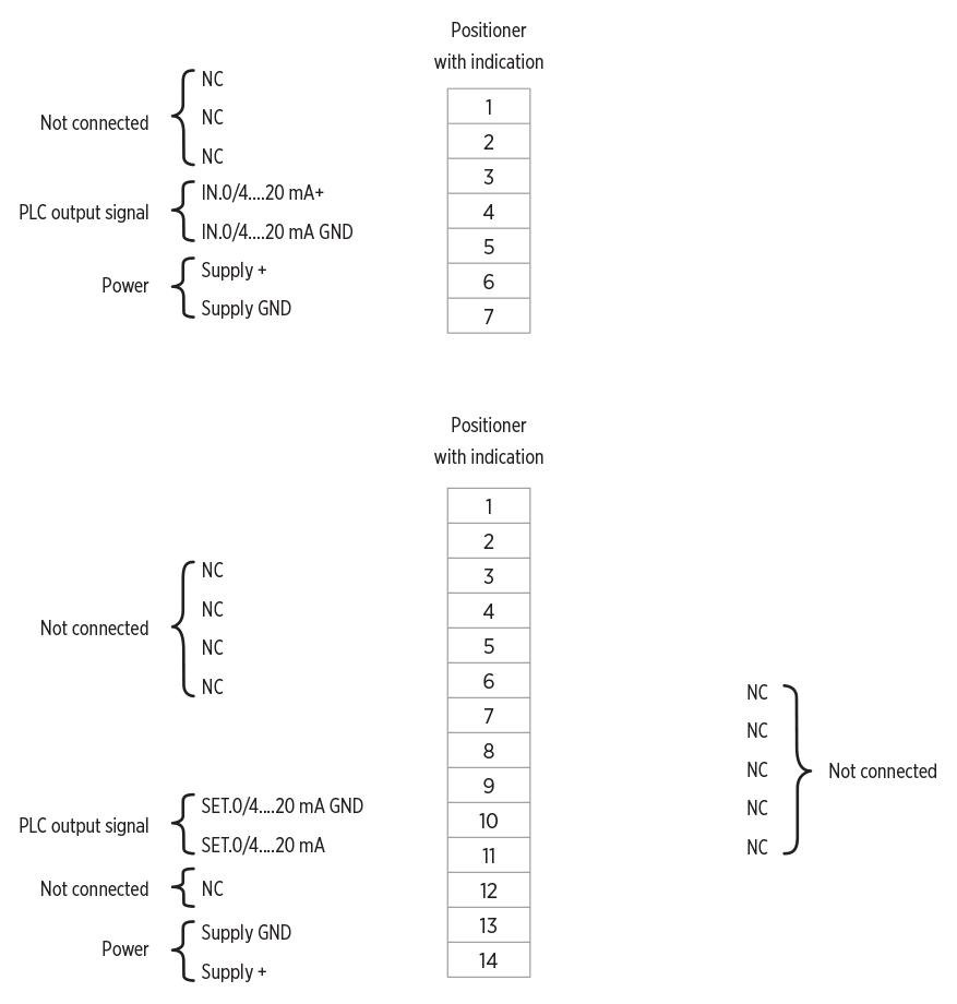
| Air Fittings Pressurized Air: R 1/8” (BSP) internal gear actuator ELECTRICAL CONNECTION |
 |